Post by: AndreasN on September 25, 2010, 08:50:36 AM
Have a question regarding minimum phase in acoustics. It's a common claim from the EQ camp that any phenomena that is indicated by a measurement system to be minimum phase is minimum phase.
Disregarding measurement systems for a while - is there a physical rationale behind such an assumption?
If a current in a voice coil makes a magnet move, that's a direct cause and consequence. That's minimum phase. So far, so good. If the membrane attached to the magnet starts flapping, it's not a direct cause->consequence, it's an indirect consequence. Ditto with edge diffraction and... Anything involving interactions between direct sound and reflections from a room! As in acoustics in general.
So how come some claim certain acoustical phenomena are minimum phase and hence can be corrected by EQ? I can't wrap my mind around this.. It seems to me that it's an outlandish claim. But I'm apt at jumping at too quick conclusion.
Thoughts?
Regards,
Andreas Nordenstam
Post by: bruno putzeys on September 25, 2010, 11:17:07 AM
| AndreasN wrote on Sat, 25 September 2010 14:50 |
It's a common claim from the EQ camp that any phenomena that is indicated by a measurement system to be minimum phase is minimum phase. |
There's no "EQ camp" claiming this. There is no such thing as a "minimum phase phenomenon". What exists is a minimum phase transfer function (=magnitude & phase response rolled into one). When, in acoustics, someone says that a measured transfer function is minimum phase they most certainly mean it's a combination of a minimum phase transfer function PLUS a pure delay (which is NOT minimum phase).
You can get an idea of whether a measured impulse response is that of a minimum phase transfer by looking at how it decays. If you see no echos or ringing bigger than the initial spike you can be reasonably sure that it's MP.
There's something pretty crucial about this. The response of a driver mounted in a cabinet, measured more or less on axis in a more or less reflection-free environment, is usually minimum phase (+delay). Turn the cabinet around and it's no longer the case. The first thing to hit the mic is the diffraction (a weak spike) followed by the first reflection which is much louder.
That's why you can't say some physical process is minimum phase. The response from the same speaker, as measured in different environments or from a different angle may or may not be minimum phase.
Minimum phase has several implications:
1) phase response can be derived directly from magnitude response and vice versa.
2) The phase responses of two MP transfer functions that have mirror-image magnitude responses (in dB), are mirror images as well.
Analogue EQ's normally have MP. If you use one to correct the magnitude response of another MP transfer function, the phase response is corrected as well. By necessity this means that the impulse response is also corrected. For instance, when designing a loudspeaker you're best off first correcting each drive unit separately, precisely because of this. A single wideband loudspeaker unit with an EQ in front of it can have a spectacularly tight impulse response, even if the same unit without EQ does not.
Non-minimum phase transfer functions can be corrected as well, to an arbitrary degree of precision but never exactly, and always at the expense of added delay. The complement of a non-minimum phase filter is a non-causal filter (one that has "pre-decay"), which can be approximated using an FIR filter provided you add as much delay as the amount of "pre-decay" you actually want to realise.
Post by: Thomas Jouanjean on September 26, 2010, 03:28:06 PM
| bruno putzeys wrote on Sat, 25 September 2010 10:17 |
When, in acoustics, someone says that a measured transfer function is minimum phase they most certainly mean it's a combination of a minimum phase transfer function PLUS a pure delay (which is NOT minimum phase). |
And a pure delay in acoustics is very hard to achieve in a studio situation, for example because of the material's density vs behaviour with regards to different frequencies.
Post by: AndreasN on September 27, 2010, 07:35:06 AM
| bruno putzeys wrote on Sat, 25 September 2010 17:17 |
There's no "EQ camp" claiming this. There is no such thing as a "minimum phase phenomenon". What exists is a minimum phase transfer function (=magnitude & phase response rolled into one). When, in acoustics, someone says that a measured transfer function is minimum phase they most certainly mean it's a combination of a minimum phase transfer function PLUS a pure delay (which is NOT minimum phase). |
Thanks for the clarifications!
Sorry for the poor phrasing in the original post. What I was trying to address is the link between observation system and reality. Don't want to mention names here. There are however, in the room EQ industry, a typical assumption that parts of a room response is close enough to "being" minimum phase. Close enough that the resulting observed aberrations in frequency response can be corrected by minimum phase IIR filters where the poles and zeroes are set by virtue of the seemingly "minimum phase" behaviour in parts of the observed response. Typically done by finding areas where the excess phase calculation is flat. In other words, looking for "a pure delay + minimum phase" response in the room and then disregard the "pure delay" part.
It doesn't seem to me that it's a procedure that have any physical basis. How is a delay+minimum phase response supposed to be corrected by a pure minimum phase response?
(didn't intend to mention names, but here's an example to make it clearer)
Post by: bruno putzeys on September 27, 2010, 09:50:48 AM
As your link shows, people run a lot of numbers on these problems whilst utterly failing to grasp the fundamental issues. Running through the text (approx. 20 seconds) I think their understanding of minimum phase etc is good enough, but the link between "minimum phase regions" and sensibility of room EQ is assumed, not demonstrated.
Post by: AndreasN on September 27, 2010, 10:31:26 AM
| bruno putzeys wrote on Mon, 27 September 2010 15:50 |
I think their understanding of minimum phase etc is good enough, but the link between "minimum phase regions" and sensibility of room EQ is assumed, not demonstrated. |
This touches one of the most interesting aspects of room EQ'ing/DSP. There is actually a continual stream of practical tests that "proves" that the applied EQ/DSP treatment works as intended. It's a circular argument; using the same contrived observational setup to evaluate the problem, the treatment and the effect of the treatment.
A typical "proof of virtue" is to show that standing waves are hitting the noise floor at some earlier time than previously measured. Exactly what one expects when putting less energy into the system at the resonant frequency!
As frequency response is commonly evaluated using relatively long windows, the same circular argument is oftentimes found in that area.
Post by: Ethan Winer on September 27, 2010, 02:33:42 PM
| AndreasN wrote on Mon, 27 September 2010 10:31 |
There is actually a continual stream of practical tests that "proves" that the applied EQ/DSP treatment works as intended. |
Andreas, I know you're aware of my position on this. I'm not a math guy like you and Bruno and others, so all I can do is actually test the claims. When I did that (LINK) the claims were proven false. It might be possible to tweak DSP to reduce ringing at the microphone position, though I was never able to confirm that either. Regardless, when you move the microphone even one inch all the ringing comes back. So what's the point?
--Ethan
Post by: bruno putzeys on September 27, 2010, 04:26:37 PM
| Ethan Winer wrote on Mon, 27 September 2010 20:33 |
So what's the point? |
The quotes, I think.
Post by: Geoff Emerick de Fake on September 28, 2010, 08:32:47 AM
| AndreasN wrote on Mon, 27 September 2010 06:35 | ||
Thanks for the clarifications! Sorry for the poor phrasing in the original post. What I was trying to address is the link between observation system and reality. Don't want to mention names here. There are however, in the room EQ industry, a typical assumption that parts of a room response is close enough to "being" minimum phase. Close enough that the resulting observed aberrations in frequency response can be corrected by minimum phase IIR filters where the poles and zeroes are set by virtue of the seemingly "minimum phase" behaviour in parts of the observed response. Typically done by finding areas where the excess phase calculation is flat. In other words, looking for "a pure delay + minimum phase" response in the room and then disregard the "pure delay" part. It doesn't seem to me that it's a procedure that have any physical basis. How is a delay+minimum phase response supposed to be corrected by a pure minimum phase response? (didn't intend to mention names, but here's an example to make it clearer) |
Note: I assume here for simplification that direct signal is time-normalised at the listening position, hence qualified of "undelayed".
Many people think that since many acoustic problems are caused by delays and combination of non-delayed and several differently delayed signals, the cure can only be using time-delay techniques to fix them.
Although this may be philosophically true if one wants to address the whole frequency spectrum, it turns out that, at lower frequencies, the effect of combining these signals is merely a modification of the frequency (and phase) response that can generally be addressed by rather conventional EQ techniques. It is clear that, if we consider the simplest comb-filtering effect, which shows complete phase-cancellation when two signals of equal amplitude are delayed by a half-wave, there is no way an EQ would fix this (the least difficult aspect being capable of producing infinite boost).
But in fact, it has largely been demonstrated that up to half the cancellation frequency, standard EQ can be applied, that will correct both amplitude and phase response.
In a real-world situation, there are an infinite number of reflections, but generally, there's not one of sufficient amplitude to introduce complete phase-cancellation, but rather a series of smaller reflections of more or less spread delay, which a good acoustic designer will "tame" in order to make them closer to minimum-phase behaviour, and as a consequence, more EQ-friendly.
Indeed, it is not possible to solve delay-related problems with EQ at MF and HF, but neither is it actually practically doable with delay techniques.
Most of the "reverse impulse response techniques" end up doing just about the same as their purely EQ counterparts. Those techniques that are supposed to work at MF are plagued with a too-narrow sweet spot.
Post by: JohnM on October 02, 2010, 06:15:28 PM
| AndreasN wrote on Mon, 27 September 2010 12:35 |
Sorry for the poor phrasing in the original post. What I was trying to address is the link between observation system and reality. Don't want to mention names here. There are however, in the room EQ industry, a typical assumption that parts of a room response is close enough to "being" minimum phase. Close enough that the resulting observed aberrations in frequency response can be corrected by minimum phase IIR filters where the poles and zeroes are set by virtue of the seemingly "minimum phase" behaviour in parts of the observed response. Typically done by finding areas where the excess phase calculation is flat. In other words, looking for "a pure delay + minimum phase" response in the room and then disregard the "pure delay" part. It doesn't seem to me that it's a procedure that have any physical basis. How is a delay+minimum phase response supposed to be corrected by a pure minimum phase response? (didn't intend to mention names, but here's an example to make it clearer) |
Since I'm the author of your example text, I thought I should respond. That text was written to help non-technical users gain a basic understanding of what minimum phase means. I would not consider myself to be "in the room EQ industry", not least because I make my living in an unrelated industry and provide the REW software without charge. The "Room EQ Wizard" name dates back to the origins of the code about 8 years ago, when it was aimed at helping users of parametric EQ visualise the effect their settings would have on a response. It has since developed into an acoustic measurement package, but still offers tools to examine the effects of and configure equalisers. My position on the merits of EQ should be fairly clear from this article, which is also part of the help text you linked to: Why can't I fix all my acoustic problems with EQ?. The reason for largely disregarding delay in the minimum phase article is that the bulk of the delay is typically a time of flight issue in the measurement setup rather than inherent in the system being measured, and is not something that would be "seen" by an equaliser in series with the original system, particularly when looking at the subwoofer range where EQ can provide useful benefit. The delay also has no effect on the locations of the poles of the transfer function, which is where EQ should be targeted.
Best regards,
John
Post by: JohnM on October 02, 2010, 06:33:27 PM
| AndreasN wrote on Mon, 27 September 2010 15:31 |
A typical "proof of virtue" is to show that standing waves are hitting the noise floor at some earlier time than previously measured. Exactly what one expects when putting less energy into the system at the resonant frequency! |
Post by: Thomas Jouanjean on October 04, 2010, 05:58:15 PM
Most designers know indeed how to "tame" all these problems, but let's be honest here, there are no miracles. Just educated compromises.
When I think about subjects like minimum phase which are being discussed a lot on some forums (it is THE buzz word lately it seems!) I cannot help but (still) be surprised that in the light of these discussions some of the wild numbers claimed every now and then when it comes to room responses are not questioned. Who can seriously claim responses within 3dB and be taken seriously? Basic floor, console surface and other random reflections will impose variations of anywhere between +/- 3 and 6dB at best.
If you're reaching a stable response within the 10/12dB benchmark in a control room, it is quite an achievement. I've noticed that all rooms that exceed these numbers (which is expensive) are getting dull and lifeless pretty fast, which isn't a good thing.
In short, I'm happy subjects like non-minimum phase are brought to the table because it allows a reality check - which is more and more needed in this field.
Another important subject that is never discussed is re emission (stress energy release via a given material) and damping to manage it.
'nyway, thanks all
Post by: bruno putzeys on October 05, 2010, 02:45:26 AM
| JohnM wrote on Sun, 03 October 2010 00:15 |
My position on the merits of EQ should be fairly clear from this article, which is also part of the help text you linked to: Why can't I fix all my acoustic problems with EQ?. |
Indeed, you do mention the fatal flaw in room EQ in the linked text. But to me that's precisely what it is: fatal
| JohnM wrote on Sun, 03 October 2010 00:33 |
The greater the cut, the greater the difference between the decay rates of the original resonance and the filter aimed at it. |
That one bears emphasizing because both in loudspeaker EQ and in control theory I find intuition often gives out.
Post by: Geoff Emerick de Fake on October 08, 2010, 10:01:14 AM
| JohnM wrote on Sat, 02 October 2010 17:33 | ||
|
Post by: JohnM on October 08, 2010, 01:06:04 PM
| Geoff Emerick de Fake wrote on Fri, 08 October 2010 15:01 |
I don't get it... |
I suspect you may be considering this in terms of providing a perfect inverse for a room's transfer function by means of suitably chosen biquads. Whilst the TF of a room response from a specific source position to a specific receiver position can be broken down into its constituent poles and zeroes, which can then be grouped as biquads, that of course does not make it invertible - there are non-minimum phase zeroes in most such responses, even at very low frequencies, hence stable inverses do not exist whether constructed from biquads or anything else.
My post was about EQ filters however, not biquads in general. EQ filters have constraints on their biquad coefficients to allow them to function as intended, they do not allow independent placement of the filter poles and zeroes. I'll illustrate this with some Z-plane plots (I operate in a sampled data world
As it seems I can only upload 1 file per post, I'll continue this in another couple of posts below.
Post by: JohnM on October 08, 2010, 01:07:32 PM
Post by: JohnM on October 08, 2010, 01:10:11 PM
If this filter were being used to target a 15dB response resonance at 50Hz whose decay time was 433ms (and hence had a pole at the 50Hz, 433ms position), the filter setting of 15dB cut and Q=4.15 would place the zero on the resonance pole, cancelling it, leaving us with the filter’s pole – but the filter’s pole has a 60dB decay time of only 77ms, so the net effect has been to replace a 433ms decay time and 15dB peak with a flat response (in that region) and 77ms decay.
Post by: JohnM on October 08, 2010, 01:26:00 PM
Post by: JohnM on October 08, 2010, 01:28:18 PM
Post by: JohnM on October 08, 2010, 01:30:03 PM
Post by: JohnM on October 08, 2010, 01:33:52 PM
P.S. Between having to use a separate post for every image and having to wait a while between posts to avoid triggering the "post flood" detector, posting on here is a bit of a chore. Maybe I should be a bit less visual
Post by: Constantin on October 08, 2010, 01:39:37 PM
I will need some time to translate and understad this topic, but this is a important topic when it comes to listening room design.
thanks again
cheers
constantin
Post by: jimmyjazz on October 08, 2010, 09:18:42 PM
Post by: JohnM on October 09, 2010, 02:33:11 AM
| jimmyjazz wrote on Sat, 09 October 2010 02:18 |
In the examples you show, is anything an actual measurement, or is it all theory? |
Post by: Geoff Emerick de Fake on October 09, 2010, 06:32:56 PM
| JohnM wrote on Fri, 08 October 2010 12:06 | ||
|
| Quote: |
I suspect you may be considering this in terms of providing a perfect inverse for a room's transfer function by means of suitably chosen biquads. Whilst the TF of a room response from a specific source position to a specific receiver position can be broken down into its constituent poles and zeroes, which can then be grouped as biquads, that of course does not make it invertible - there are non-minimum phase zeroes in most such responses, even at very low frequencies, hence stable inverses do not exist whether constructed from biquads or anything else. |
| Quote: |
My post was about EQ filters however, not biquads in general. EQ filters have constraints on their biquad coefficients to allow them to function as intended, they do not allow independent placement of the filter poles and zeroes. |
| Quote: |
I'll illustrate this with some Z-plane plots (I operate in a sampled data world |
I don't understand what is an EQ filter with a gain of zero...
An EQ filter has some boost or cut, so do you mean 0dB boost (or is it cut?)??? But a flat EQ has neither poles nor zeros...although I understand that, for the sake of demonstration, you may consider a flat EQ as identical denominator and numerator, which would obviously have their zeros and poles at the same location. Which is a perfect demonstration of the interaction between zeros and poles when they are very close.
Your example showing the dramatic reduction of decay at 50Hz goes to show that there is something that reduces the overall decay of the room + EQ combo. If you took into account only the poles, you would add both decays.
In fact it is a superb demonstration that EQ can compensate some of the time-related effects of resonance, just like a 10dB cut can perfectly compensate a 10dB boost at same frequency and same BW. The way the decay at 50Hz aligns almost perfectly with the 60-90Hz range decay says for me Mission accomplished.
I deliberately don't use Q notion because it just doesn't work for EQ's. IMO it works only for RLC bandpass filters. The academic definition of Q suppose asymptotic zero response and narrow BW. Eq filters never obey the 1st condition and 2nd condition is not applicable for less than 3dB boost/cut. [/aside]
Post by: JohnM on October 09, 2010, 07:49:15 PM
| Geoff Emerick de Fake wrote on Sat, 09 October 2010 23:32 |
Basically, what I don't get is you consider the influence of poles decay and apparently neglect that of zeros. |
To address the influence of a particular modal resonance pole pair an EQ filter can be adjusted so that the filter's zeroes overlay the resonance's poles, which cancels them, effectively removing both the filter's zeroes and the resonance's poles from the TF. We are then left with the filter's poles, which, because our filter has cut, have faster decay than the poles of the resonance we started with.
| Quote: |
I don't understand what is an EQ filter with a gain of zero...An EQ filter has some boost or cut, so do you mean 0dB boost (or is it cut?)??? But a flat EQ has neither poles nor zeros...although I understand that, for the sake of demonstration, you may consider a flat EQ as identical denominator and numerator, which would obviously have their zeros and poles at the same location. Which is a perfect demonstration of the interaction between zeros and poles when they are very close. |
| Quote: |
I deliberately don't use Q notion because it just doesn't work for EQ's. IMO it works only for RLC bandpass filters. The academic definition of Q suppose asymptotic zero response and narrow BW. Eq filters never obey the 1st condition and 2nd condition is not applicable for less than 3dB boost/cut. |
Post by: Geoff Emerick de Fake on October 10, 2010, 09:45:10 AM
"common acoustical poles" seems to be a way of representing the invariant room accidents, in particular room modes, in a way that suit itself to equalization, which is the basis of this discussion. In this representation, room accidents are represented by biquads, with poles and zeroes.
Now it seems that you don't do anything with this particular biquad zeroes because they are almost an act of God
But you take into account the poles of the EQ because they are perfectly and easily accountable.
Honestly trying to understand; somewhat goes against 40 years of electronics engineering and a droplet of acoustics.
The RBJ method is interesting; it's much better than the -3dB method, which many think is an absolute truth, cast-in-stone, when in fact it shows its limits as soon as you combine a boost and a cut at the same frequency.
But personally, I use a different method, based on users expectations. I use the "1/4-the-dB" method, which in the case of +/- 12dB boost/cut EQ, is consistent with the auditive concept that 3dB is the audible corner. And I benever dare calling it Q, I refer to it as bandwidth.
Q is supposed to be a portable notion, which in fact turns out to be utterly unusable.
Post by: bruno putzeys on October 10, 2010, 11:56:00 AM
Post by: JohnM on October 10, 2010, 05:24:44 PM
| Geoff Emerick de Fake wrote on Sun, 10 October 2010 14:45 |
Tell me if I understand you well. "common acoustical poles" seems to be a way of representing the invariant room accidents, in particular room modes, in a way that suit itself to equalization, which is the basis of this discussion. In this representation, room accidents are represented by biquads, with poles and zeroes. Now it seems that you don't do anything with this particular biquad zeroes because they are almost an act of God But you take into account the poles of the EQ because they are perfectly and easily accountable. Honestly trying to understand; somewhat goes against 40 years of electronics engineering and a droplet of acoustics. |
If we could move the room TF poles further away from the unit circle we would have a response that had smaller peaks and faster decay. We can't actually alter the poles of the room TF, but what we can do is put a biquad EQ filter in the path to the source for each resonance we want to target. The filter adds its own pair of poles and its own pair of zeroes to the TF. We can adjust the EQ filter cut and bandwidth so that its zero locations fall exactly on top of a particular pair of poles in the room TF. The net effect of a pole and a zero in the same location is nil, so doing this effectively eliminates the room TF pole pair we have targeted. We are left with the pole pair of the filter itself, but the nature of EQ cut filters is that their poles are further from the unit circle than their zeroes, so overall the effect is as if we moved the room TF pole pair to the locations of the filter pole pair, where they have much smaller influence on the frequency response than they had in their original locations.
Post by: JohnM on October 10, 2010, 05:55:34 PM
| bruno putzeys wrote on Sun, 10 October 2010 16:56 |
What algorithm do you use to get from a response measurement to a p/z representation? The reasoning that the poles remain in place while the zeros shift about is entirely correct as I see it. I seem to remember our company being contacted by a Finnish joint with similar ideas. |
here. It is a parametric analysis of the impulse response to determine the set of damped complex exponentials that produce the time series, in a similar manner to ARMA modelling or Linear Predictive Coding. I've been through a variety of methods to arrive at something reasonably robust, including Decimated Signal Diagonalisation and Filter Diagonalisation, neither of which responded well to the noisy signals we are faced with in acoustic measurement. I eventually adapted a technique used in processing NMR data, but all such methods are very sensitive to the signal-to-noise ratio of the measured IR. One group of Finns developed a technique they called "Frequency Zooming ARMA" to do the job, which looks from their papers like it should work well also.
Post by: Geoff Emerick de Fake on October 11, 2010, 06:35:47 AM
| JohnM wrote on Sun, 10 October 2010 16:24 |
I think something got lost in translation there, accidents? |
| Quote: |
Anyway, the transfer function from a source position to a receiver position in a room has a numerator and a denominator. The roots of the numerator are the zeroes of the TF, the roots of the denominator are the poles, which correspond to individual resonant frequencies in the TF. The closer the poles are to the unit circle in the Z plane or the imaginary axis in the S plane, the slower the associated resonance decays and the greater the peak in the frequency response due to that particular resonance - the overall response is the combined effect of all the poles and zeroes of course, but each has its contribution. |
| Quote: |
If we could move the room TF poles further away from the unit circle we would have a response that had smaller peaks and faster decay. We can't actually alter the poles of the room TF, but what we can do is put a biquad EQ filter in the path to the source for each resonance we want to target. The filter adds its own pair of poles and its own pair of zeroes to the TF. We can adjust the EQ filter cut and bandwidth so that its zero locations fall exactly on top of a particular pair of poles in the room TF. The net effect of a pole and a zero in the same location is nil, so doing this effectively eliminates the room TF pole pair we have targeted. |
| Quote: |
We are left with the pole pair of the filter itself, but the nature of EQ cut filters is that their poles are further from the unit circle than their zeroes, so overall the effect is as if we moved the room TF pole pair to the locations of the filter pole pair, where they have much smaller influence on the frequency response than they had in their original locations. |
I understand when you say "I am not attempting to do anything about the zeroes of the room transfer function", I understand you can't change them, but my understanding is that the algorithm "translates" the actual RTF into a set of biquads with a set of poles and zeroes. My gut feeling is that the correcting EQ should have its zeroes and poles at the same location and they would both cancel.
Post by: JohnM on October 11, 2010, 09:25:54 AM
| Geoff Emerick de Fake wrote on Mon, 11 October 2010 11:35 |
That's where I lose you (or you lose me). What do you do with the zeroes of the biquad that is derived from the actual RTF? I understand when you say "I am not attempting to do anything about the zeroes of the room transfer function", I understand you can't change them, but my understanding is that the algorithm "translates" the actual RTF into a set of biquads with a set of poles and zeroes. My gut feeling is that the correcting EQ should have its zeroes and poles at the same location and they would both cancel. |
The other half of the answer concerns what tools we have in the toolbox. What is readily available are parametric EQ filters. The parameters you can adjust are the centre frequency, gain and bandwidth or Q. As you adjust those parameters the corresponding poles and zeroes of the filter move. There is no way with a parametric EQ filter to adjust the poles independently of the zeroes, they are inextricably linked. When you have adjusted a filter so its zeroes lie on the poles of a room TF resonance, the poles of the filter are always further from the unit circle than the zeroes, and the bigger the cut that was applied the further away from the unit circle those poles end up. You cannot leave the filter zeroes in their desired location and start shifting the poles about to a convenient spot. Fortunately, the locations the filter poles end up in means they have fast decay and little effect on the frequency response, so overall there has been a substantial improvement in the frequency response and time domain behaviour of the TF in the region where the parametric EQ filter was applied, for the position at which the TF was measured.
Post by: Bogic Petrovic on October 11, 2010, 10:24:54 AM
| JohnM wrote on Mon, 11 October 2010 15:25 |
........ If the aim was to produce a perfect inverse of the room TF then you would indeed want to put zeroes on all the poles and poles on all the zeroes, literally invert the TF. That, however, is not possible. Room TF's have zeroes that are outside the Z plane unit circle/in the right half of the S plane. Poles in such locations would be unstable (their damping would be negative). So half of the answer is that this is not an attempt to make a perfect inverse because that cannot be done. ...... |
Yes . . . you're right.
I even try
This is one of reasons why we need better algorithms than this
Post by: Geoff Emerick de Fake on October 11, 2010, 12:15:56 PM
| JohnM wrote on Mon, 11 October 2010 08:25 | ||
|
Post by: AndreasN on October 12, 2010, 08:38:40 AM
I owe you an apology. It wasn't the best style to link to your text without giving you a notice. Glad you found your way to this thread! Am much obliged to your splendid effort with REW. It's a charm to use and it's sure a generous gesture to put it out for free. Much appreciated!
Hope you don't misunderstand that part. It's a great analytical tool. What I'm questioning is not the system itself(except for the modal T60 calculations post filtering, more on that below). The question is how the observed results relates to reality.
Real life is a signal leaving a speaker and bouncing around in a room. Modal response, standing waves, are waves passing the measurement mic at regular intervals. A reflective rectangular room will have clearly audible flutter echo from speaker to listener. That's the high frequency sound of a broadband lump of energy bouncing back and forth at regular intervals. Standing waves are typically filtered more towards the low end, but it's still "wave packets" of energy passing the sweet spot at regular intervals. That this repetition rate happens to be this or that Hertz is the product of the waves passing the microphones at those intervals. Not other way around! There's no "Hertz" in reality, only energy changes across time.
"When you have a hammer, everything looks like a..." The ability to view a room response as a frequency domain response doesn't mean that the real world behaviour IS a frequency domain behaviour. The same goes for the Z plane.
An arbitary set of FIR taps can have any response in time domain, including very long ones. Minimum phase filtering will invariably give a very short time response compared to the acoustic response. Having a single short impulse response altering the signal can not, even in the 2D world of digital signal processing, do anything to the long time behaviour. The rate of decay is still constant! The EQ can't do anything about the room and it can't change the rate of decay.
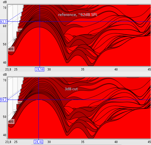
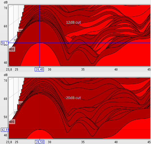
Looking at the calculated before/after filtering in the waterfall plots in REW confirms this. I've looked at the simulations for several different rooms and the results are the same. A -10dB EQ cut shows up as a -10dB cut across the whole decay range. It doesn't increase the rate of decay.
The modal EQ part in REW seems to calculate a shortening in decay rate that corresponds directly to the EQ cut in deciBels. Ie, -6.02 dB is half decay time and -12.04 dB is one fourth decay time, and so on. The ability to do such a calculation doesn't mean that the real world behaves that way. The plots in the waterfal tells another story than the EQ filters indicate. Please have a better look at what the changes does to the response if you don't believe me. I've looked at several different rooms and there's no doubt: the EQ does work like one expects from an EQ, giving the same cut or boost across all time, not increasing the cut or boost as time passes..
The situation is akin to strapping an EQ in front of a reverb unit. Twisting the EQ knobs can't change the amount of feedback circulation in the reverb patch following the EQ. Changing the sound of the 'verb unit needs to be done inside the 'verb system by altering the strenght of the feedback. Or, in real life, altering the strength of reflections in a room.
EQ'ing will do exactly what one expects based on general signal processing experience: more or less level of the relevant frequencies across all time. Cutting in the direct signal to counteract standing waves will leave a hole in the direct signal.
If the EQ could actually affect the decay rate, it would have to involve "cancellation impulses". And we all know how well that stuff works..
So I'm still utterly unable to see how minimum phase have any real world connection to room acoustics!
Best regards,
Andreas Nordenstam
Post by: AndreasN on October 12, 2010, 10:11:35 AM

| Quote: |
Now we have something we can work with. Anywhere the excess group delay plot is flat is a minimum phase region of the response. |
I've also looked at this aspect in several different room measurement. The only way I can find any part of the excess group delay to "be flat" is by not looking hard enough. As I zoom in, the response observed is never flat in any region of any room responses.
Post by: JohnM on October 12, 2010, 11:06:48 AM
| AndreasN wrote on Tue, 12 October 2010 13:38 |
Real life is a signal leaving a speaker and bouncing around in a room. Modal response, standing waves, are waves passing the measurement mic at regular intervals. A reflective rectangular room will have clearly audible flutter echo from speaker to listener. That's the high frequency sound of a broadband lump of energy bouncing back and forth at regular intervals. Standing waves are typically filtered more towards the low end, but it's still "wave packets" of energy passing the sweet spot at regular intervals. That this repetition rate happens to be this or that Hertz is the product of the waves passing the microphones at those intervals. Not other way around! There's no "Hertz" in reality, only energy changes across time. |
| Quote: |
Minimum phase filtering will invariably give a very short time response compared to the acoustic response. |
| Quote: |
Having a single short impulse response altering the signal can not, even in the 2D world of digital signal processing, do anything to the long time behaviour. The rate of decay is still constant! The EQ can't do anything about the room and it can't change the rate of decay. |
| Quote: |
Looking at the calculated before/after filtering in the waterfall plots in REW confirms this. I've looked at the simulations for several different rooms and the results are the same. A -10dB EQ cut shows up as a -10dB cut across the whole decay range. It doesn't increase the rate of decay. |
| Quote: |
The modal EQ part in REW seems to calculate a shortening in decay rate that corresponds directly to the EQ cut in deciBels. |
| Quote: |
Cutting in the direct signal to counteract standing waves will leave a hole in the direct signal |
Post by: JohnM on October 12, 2010, 11:10:00 AM
| AndreasN wrote on Tue, 12 October 2010 15:11 | ||
PS, this part of your text is also a bit strange:
I've also looked at this aspect in several different room measurement. The only way I can find any part of the excess group delay to "be flat" is by not looking hard enough. As I zoom in, the response observed is never flat in any region of any room responses. |
Post by: JohnM on October 12, 2010, 02:14:09 PM
Post by: Geoff Emerick de Fake on October 12, 2010, 06:44:32 PM
| AndreasN wrote on Tue, 12 October 2010 07:38 |
The situation is akin to strapping an EQ in front of a reverb unit. Twisting the EQ knobs can't change the amount of feedback circulation in the reverb patch following the EQ. Changing the sound of the 'verb unit needs to be done inside the 'verb system by altering the strenght of the feedback. Or, in real life, altering the strength of reflections in a room. |
| Quote: |
So I'm still utterly unable to see how minimum phase have any real world connection to room acoustics! |
In your original post, you mentioned a membrane flapping: it is obvious that no EQ can correct this because it is both non-linear and time-variant, but reflections are enough linear and time-invariant, when they are significantly shorter than the period of the signal.
Then, if the response has the shape and phase of a biquad, it is a biquad as far as processing is concerned.
Post by: Geoff Emerick de Fake on October 12, 2010, 06:58:30 PM
| AndreasN wrote on Mon, 27 September 2010 06:35 |
There are however, in the room EQ industry, a typical assumption that parts of a room response is close enough to "being" minimum phase. Close enough that the resulting observed aberrations in frequency response can be corrected by minimum phase IIR filters where the poles and zeroes are set by virtue of the seemingly "minimum phase" behaviour in parts of the observed response. Typically done by finding areas where the excess phase calculation is flat. In other words, looking for "a pure delay + minimum phase" response in the room and then disregard the "pure delay" part. It doesn't seem to me that it's a procedure that have any physical basis. How is a delay+minimum phase response supposed to be corrected by a pure minimum phase response? |
Post by: AndreasN on October 15, 2010, 08:05:17 AM
Quick notice to say that this thread is not forgotten.
Am mailing back and forth with John now. Will get back to the issues in this thread when I've learned some more and heard what John thinks about my ideas.
Andreas
Post by: AndreasN on October 26, 2010, 02:44:35 PM
So.. I've received excellent coaching from John via email. It really seems the minimum phase EQ's can and do change the rate of decay for the boosts caused by standing waves.
Have been discussing EQ'ing and room correction with various folks over the last year. None in the "EQ camp" have been able to provide any sort of evidence like that. My hat is of to John for finally making some sense out of one aspect of room EQ'ing! Namely: to tame low frequency peaks caused by standing waves.
The price: punching a hole in the direct sound.
It may be a worthwhile trade off in some circumstances.
There's also some other issues. More on that below.
| JohnM wrote on Tue, 12 October 2010 17:06 |
This is incorrect. To be pedantic, the time response of a typical IIR filter is, well, infinite |
This was one of the biggest surprises in this exercise. Have of course looked at EQ impulse responses before, but I tend to use way lower Q's. The extremely long responses of the high Q low F filters explains a lot.
| Geoff Emerick de Fake wrote on Tue, 28 September 2010 14:32 |
Most of the "reverse impulse response techniques" end up doing just about the same as their purely EQ counterparts. Those techniques that are supposed to work at MF are plagued with a too-narrow sweet spot. |
Right on. Basically, it boils down to the EQ giving a sort of impulse cancellation across a rather long stretch of time.
Which makes me wonder.. Cancelling stuff in the computer is all fine and cancelling at the point of an omni microphone is fine. But what about the hearing system? The ability to hear direction at low frequency isn't good, but it's not totally gone before one hits the lowest octave or so. This may be an issue, or it may not be an issue.
In any case, the situation is one where positive pressure is cancelled with negative pressure, and vice versa. How does it feel compared to simply having less pressure fluctuations in the first place? Listener fatigue comes to mind.
| JohnM wrote on Tue, 12 October 2010 17:06 | ||
|
I think this deserves more discussion. Integrating 20ms (1/50Hz) is pretty common. Integrating several hundreds of milliseconds, as in a typical standing wave boom, seems a bit far fetched to me. Haven't read any particular tests on this or done much study on my own. From what I've gleamed, it seems that standing waves are heard more as a separate boom than an aural entity that fuse with direct sound like early reflections do.
Anyone?
| JohnM wrote on Tue, 12 October 2010 17:10 | ||||
|
This situation is different. If looking at a pure minimum phase response, the excess phase plot is absolutely flat no matter how far one zooms in.
"Being sorta minimum phase" is obviously not the same as being minimum phase. At what point is the excess phase plot flat enough? 10 millisecond deviation? 1 millisec? 0.1 ms? It doesn't seem to hold up to scrutinous analysis.
Another strange thing is that all the excess phase plots I've looked at, from real rooms, tends to be flatter in the high end than the low end. If one is to take this literally, EQ'ing high end should be better than EQ'ing low end.. We know it doesn't work that way.
| Geoff Emerick de Fake wrote on Wed, 13 October 2010 00:44 |
In your original post, you mentioned a membrane flapping: it is obvious that no EQ can correct this because it is both non-linear and time-variant, but reflections are enough linear and time-invariant, when they are significantly shorter than the period of the signal. Then, if the response has the shape and phase of a biquad, it is a biquad as far as processing is concerned. |
Hmm.. Shorter than the period of the signal? Impulses doesn't have periods.
Post by: Geoff Emerick de Fake on October 26, 2010, 04:45:31 PM
| AndreasN wrote on Tue, 26 October 2010 13:44 | ||
Hmm.. Shorter than the period of the signal? Impulses doesn't have periods. |
Post by: JohnM on October 26, 2010, 05:43:23 PM
| AndreasN wrote on Tue, 26 October 2010 19:44 |
"Being sorta minimum phase" is obviously not the same as being minimum phase. At what point is the excess phase plot flat enough? 10 millisecond deviation? 1 millisec? 0.1 ms? It doesn't seem to hold up to scrutinous analysis. |
| Quote: |
Integrating 20ms (1/50Hz) is pretty common. Integrating several hundreds of milliseconds, as in a typical standing wave boom, seems a bit far fetched to me. |
Post by: Bogic Petrovic on October 26, 2010, 11:16:36 PM
| AndreasN wrote on Tue, 26 October 2010 20:44 |
........ Another strange thing is that all the excess phase plots I've looked at, from real rooms, tends to be flatter in the high end than the low end. If one is to take this literally, EQ'ing high end should be better than EQ'ing low end.. We know it doesn't work that way. ........ |
I generally agree with you, and I believe that reason for this lies in fact that it's much easier to absorb and/or diffuse high frequencies than low frequencies. (when we talk about reflections)
From my experience classic absorption and diffusion in rooms is a way to make acoustical response in room with somewhat less non-minimum phase behavior...
Idea is: even if we can't get a flat response in that way, with classical acoustic treatment, we can "kill" most of non-minimum phase room behavior ... and rest of treatment can be done with IIR equalization (as we discuss in this thread)
I'll show you measurements from one tiny room we're doing recently. Measurements isn't done by REW but we imported wav impulses and doing analysis.
Unfortunately I don't have measurements without acoustical treatment, but I'm sure that you can use your imagination and/or your experience for understanding what response you can get from empty room with dimensions 3.56x3.67x2.55m (i repeat, this is a dimensions of an empty room)
I hope this helps for an understanding of acoustical room behavior and importance of classical acoustic room treatment, where signal level room equalization, can continue to improve response, when classical acoustical methodologies reach his limits in very small rooms.
regards
boggy
p.s. i can't do analysis without smoothing... REW ignore my attempts to switch off smoothnig... best i can get is 1/48 octave smoothing
Post by: JohnM on October 27, 2010, 04:01:42 AM
| Bogic Petrovic wrote on Wed, 27 October 2010 04:16 |
p.s. i can't do analysis without smoothing... REW ignore my attempts to switch off smoothnig... best i can get is 1/48 octave smoothing |
Post by: Bogic Petrovic on October 27, 2010, 07:02:12 AM
| JohnM wrote on Wed, 27 October 2010 10:01 |
.........Boggy, in the REW Analysis Preferences uncheck the "Allow 96PPO Log spacing" box. That option allows REW to convert measurements to a 96PPO log spaced format if that reduces storage, but requires that the measurements be filtered to 48PPO. If you uncheck the box and just re-apply the IR windows you should get an unsmoothed response. |
Thank you very much John, here are unsmoothed results:
regards
Boggy
Post by: Geoff Emerick de Fake on October 27, 2010, 01:29:07 PM
| AndreasN wrote on Tue, 26 October 2010 13:44 |
In any case, the situation is one where positive pressure is cancelled with negative pressure, and vice versa. |
| AndreasN wrote | ||||||
This situation is different. If looking at a pure minimum phase response, the excess phase plot is absolutely flat no matter how far one zooms in. "Being sorta minimum phase" is obviously not the same as being minimum phase. At what point is the excess phase plot flat enough? 10 millisecond deviation? 1 millisec? 0.1 ms? It doesn't seem to hold up to scrutinous analysis. |
At what point is the deviation from flat response audible, 0.5dB, 1dB, 3dB? Even that is not simple. A 20dB cut of 1/100 octave is inaudible for 9 persons out of 10.
The whole idea is to break the room response in a number of factors, some being minimum-phase, the others being non minimum-phase, and to apply some EQ to counteract the minimum-phase ones. For the others, the solutions are not electronic.
I think you are taking a too extreme view of this issue. We know that it's impossible to perfectly cancel out the imperfections in a room, but there are two attitudes facing this dilemma:
one is to try and make the best of what is available, the other is, like you, say that it's impossible and do nothing about it.